Traverse Global v11.2 - Service Repair
Inspection Walk-Through Tutorial
There are a number of functions that work together to provide a useful inspection process for service repair orders. This is a walk-through tutorial to help illustrate how the various processes work together in the inspection process.
This topic is intended as an overview of the workflow for the inspection process, and is not meant as a comprehensive training guide. If you want additional training regarding the configurator, inspections, or designing inspection reports, contact your software provider.
Configurator
The first step in creating an inspection is planning the details. You use the Configurator function to create an inspection. You can find detailed information on this process in the Configurator Basic Functionality topic and the Service Repair Configuration topic. Use those topics to help you configure an inspection.
Sample Configuration for tutorial


Inspection Defaults
Use the Inspection Defaults function to select service repair inspections for a selected job type. This allows the system to automatically create an inspection record when you add a new job in the Job Transactions function.
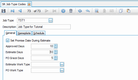
Create a new Job Type Code to use with the tutorial. The Job Type Codes function is located on the Service Repair Codes Maintenance screen.
Next, assign the inspection you configured for the tutorial to the job type you just created using the Inspection Defaults function on the Service Repair Inspections menu.

Min/Max Values
If your inspection depends on tolerances (min/max values), set up your min/max table(s) using the Min/Max Values function on the Service Repair Inspections menu. We are not going to use min/max values for the tutorial.
Inspection Report Designer
Before we can associate an inspection report layout with an inspection (configuration), we need to create a report layout for the inspection. Use the Report Designer in Design Studio to create a report layout.
The Inspection Report Designer is listed on the Inspections menu.

Choose the Inspection Report Designer from the list and use the Design button on the toolbar.
In the popup window that appears, select the tutorial configuration from the Config Desc drop-down list. Leave the Inspection Descr blank, since the inspection is not tied to a job at this point.

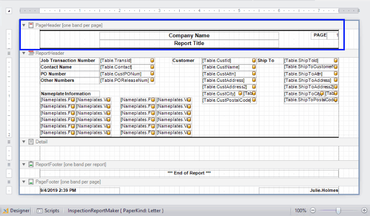
The Report Layout window opens the default report layout with standard header fields included. The fields for the inspection you have chosen are displayed in the Field List pane.

The default report layout gives you a starting point for your inspection report. Let's add a company logo to the layout. If you want the company logo to appear on every page of the report, add the logo to the PageHeader. To have the company logo appear once at the beginning of the report, add the logo to the ReportHeader.
Since the company name is in the PageHeader band, meaning it will appear on all pages of the report, it makes sense to put the company logo there as well.
Open the Tool Box panel on the left side of the designer. Click and drag a Picture Box control onto the report where you want to add the logo. For the tutorial, drag a picture box control into the PageHeader.

To make the PageHeader section bigger to better accommodate the logo picture box, drag the bottom border of the PageHeader band until the section is as large as you want. Note there is a panel control (container control) in the section that contains the other controls. Select the bottom edge of the panel and stretch it to match the height of the PageHeader. Likewise, select the bottom line and move it down. This keeps the general formatting of the page header.

Adjust the size of the picture box by selecting the control and dragging the edges. With the picture box control selected, click on the arrow to open the Picture Box Tasks window.
The Image field is where you choose the image file that will display in the picture box control. Use the ellipsis to browse for the logo file. Select the logo file. In the Sizing field, select "Stretch Image" from the drop-down list. This allows the image to be adjusted to fit the picture box.

Move the other controls in the PageHeader as needed.

To add the questions and answers from the configuration onto the report, select and resize the Detail band. In the Field List panel, there are two fields for every question on the inspection. Drag and drop the fields onto the report in the Detail band. Adjust the field controls as needed. Remember to change the sizing property of the picture boxes to "Stretch Image".
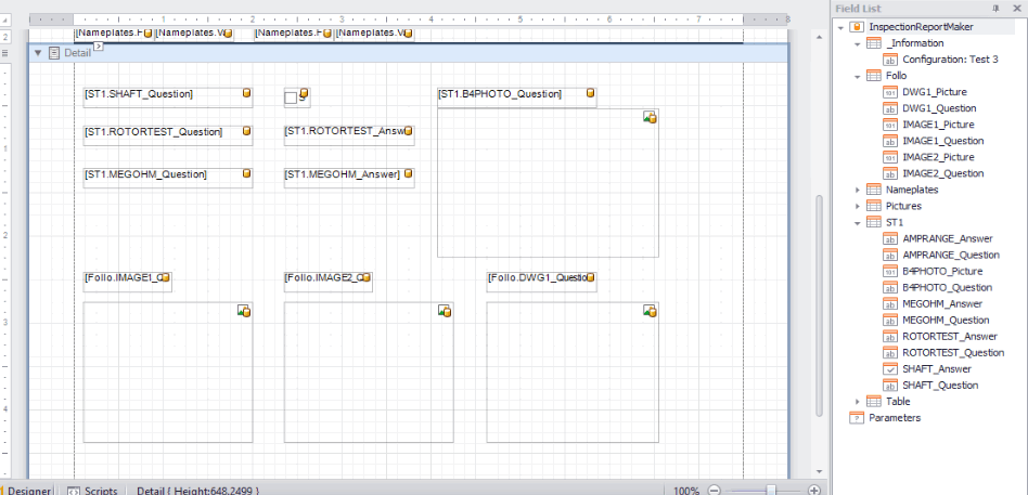
You can add additional pictures, as well as a signature to the report. The pictures and signature fields are in the Pictures branch of the Field List. Reminder: In order for a picture to appear on the report, there must be a control for it. It is recommended to add up to eight images as a standard to an inspection report. If you know for certain a particular inspection will have more than 8 images on a regular basis, then add as many additional image controls as needed. If there are more image controls on the report than there are pictures, such as only 3 pictures but 8 image controls on the report, the extra image controls will be blank (but the space will still be allocated to those image controls) when the report is printed. This means if there are fewer pictures than image controls, there will be white space on the report where the empty image controls are.
Be aware the picture box controls created when you drag pictures onto the report will have no labels describing what they are. You can add labels to the report if needed by dragging label controls from the Tool Box panel onto the report.
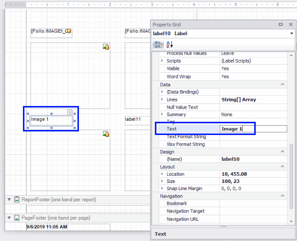
To set the text that appears in the labels, open the property grid for the label by right-clicking on the label and selecting Properties from the menu. Find the Text property in the property grid and change the value to something appropriate. In this example, the label says "Image 1" because the picture box control below it is bound to Image1 in the Field List. The property grid is also where you will find options for font and font size, justification, and many other properties.
Once you have finished the layout for the inspection report, save the report. Make sure you clear the Use default layout name check box. Enter a descriptive name in the Layout Name field. Click OK to save your inspection report layout.

Inspection Reporting
The next step is to tie the inspection report layout to a configuration in Traverse. In the Inspection Reporting function on the Service Repair Inspections menu, select the inspection report layout from the Layout Name drop-down list. Select the same configuration you chose in the Report Designer. The Job Inspection is not applicable to this tutorial; selecting an inspection on a job transaction would tie the layout to that single job transaction.
Tip: If the inspection report doesn't print right, double-check that the configuration/inspection in the Inspection Reporting screen matches the configuration/inspection selected for the report layout in the Report Designer in Design Studio.
Enter the number of pictures on the inspection report layout. This refers to the additional pictures from the Pictures branch of the Field List from the Report Designer.

Save your changes.
Job Transaction
Enter a new job transaction. For our testing purposes, we will select a random Customer ID and a random Department from the drop-down lists.
For the Job Type, select the job type we created at the beginning of the tutorial. Our inspection is tied to this job type by default (Inspection Defaults function).
Enter test information for nameplate data, ship-to, and estimate line items.
Note the job transaction number and save the job.

Inspections
Open the Inspections function and select the job transaction number you just created. The inspection groups will appear in the detail grid at the bottom of the screen.

To edit the inspection, click Edit Inspection on the toolbar. The Edit Inspection window opens. Click Expand All on the toolbar to expand the grid to show the applicable questions. Answer the questions so there is data to show on the inspection report. You can answer the questions that require an image by browsing for test images through the answer field.

Validate, then save the inspection. You will return to the Inspections screen.
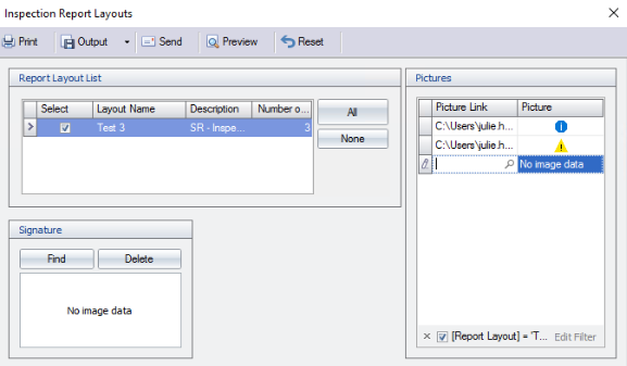
Select Print on the toolbar, then choose the Inspection Report Layouts.

The Inspection Report Layouts window will appear. Select the layout you created for the tutorial. Use the Pictures window to add additional pictures for the inspection. Notice there are the same number of entry records in the Pictures window as you entered on the Inspection Reporting screen for the inspection. You can also add one signature for each report layout in the layout list in the Signature window by clicking Find and browsing for the signature image file.
Click Preview to see the inspection report you designed.
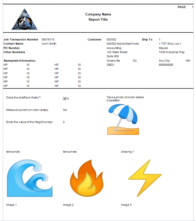

Notice the white space between the "photos" and the signature area. This is where the images (Image 1, Image 2, Image 3) are located. Because there were no actual pictures, the space occupied by the picture boxes on the report is blank, but the space is still allocated.
Now that we can see a preview of the report, we can see if there is anything we need to adjust.
Return to the Report Designer in Design Studio to fix these issues.
Open the Report Designer and select the Inspection Report Designer. Click Design on the toolbar. Select the tutorial configuration description from earlier in this topic and click OK.
When the Report Designer opens, notice it is the base template we started with. To make changes to our report layout, you will need to open that report layout. Click Open on the toolbar.
Clear the Use default layout name check box, then select the layout from the Layout Name drop-down list.

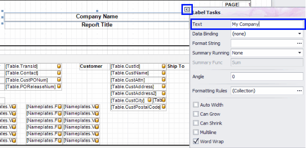
The familiar layout will open. First, add the company name and report title by selecting each control and editing the text.

Next, we need to make sure the nameplate information controls are bound to the correct fields. First, check to see which fields the controls are bound to. There are two fields for each nameplate value, a Field and a Value to match.

To check which field a control is bound to, select a control, then click the arrow to open the Label Tasks window. Move the mouse pointer over the Data Binding field in the Label Tasks window. The tooltip will show the entire binding information. The first nameplate field control is bound to Field1 in the Nameplates branch of the Field List.

The next nameplate field control to the right of the first one is bound to Value1 in the Nameplates branch of the Field List

Now check the binding for the next control down.

Notice that this control is also bound to Field1. A check of the next field shows that it is also bound to Value1. The controls need to be bound to the correct fields.
To reset the data binding, select the control and click the arrow to open the Label Tasks window. Select "Field2" from the drop-down list of the Data Binding field.

Repeat the process for all nameplate controls.
Save your changes.
To preview the report with data, select the tutorial inspection in the Inspections screen in Traverse, then click on Print and select the Inspection Report Layouts. Select the report layout and click Preview. Tip: If the report does not show your recent changes, log out of Traverse and log back in.


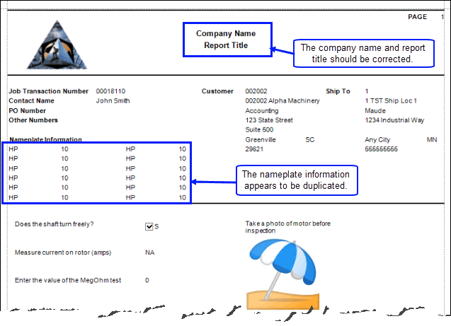
The changes we made are now reflected on the report: the report title is specific and the nameplate fields are not copies of the first field/value pair.
However, it looks like the image labels should be on the next page, where the image controls appear. We can add a page break to the report to correct this. Return to the Report Designer in Design Studio.
Open the Report Designer and select the Inspection Report Designer. Click Design on the toolbar. Select the tutorial configuration description from earlier in this topic and click OK.
When the Report Designer opens, notice it is the base template we started with. To make changes to our report layout, you will need to open that report layout. Click Open on the toolbar.
Clear the Use default layout name check box, then select the layout from the Layout Name drop-down list.
The familiar layout will open. Scroll to the location of the image label controls in the Detail band.
Open the Tool Box panel and find the Page Break control. Drag the control into place and drop it on the report layout.

Save the layout.
To preview the report with data, select the tutorial inspection in the Inspections screen in Traverse, then click on Print and select the Inspection Report Layouts. Select the report layout and click Preview. Tip: If the report does not show your recent changes, log out of Traverse and log back in.


Once the report layout is acceptable, you can use it as part of your inspection process.